This website uses cookies for analyzing traffic and improving user experience through Google Analytics. These cookies help us gather information about how you use our site. Your data is anonymized and is not used to identify users. Do you agree to the use of analytical cookies?
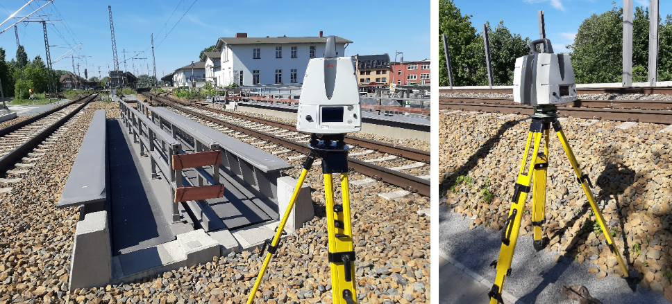
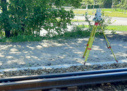
Our work is based on terrestrial laser scanning.
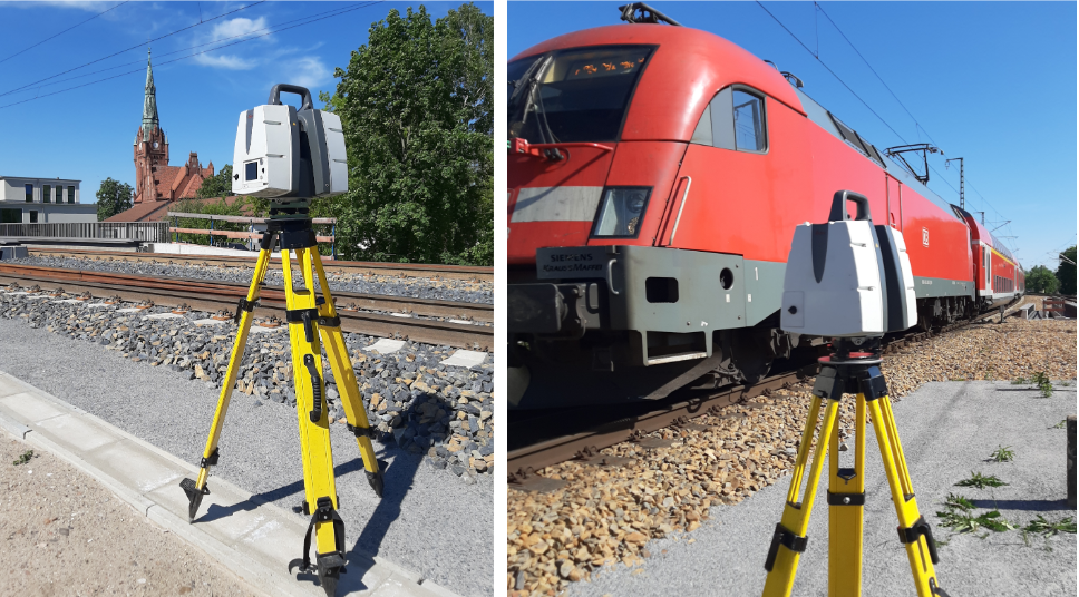
The 3D scanner is positioned at carefully selected locations to capture the entire object.
This method forms the foundation of reliable and highly accurate deliverables.
Over the years, we have worked with various scanners, including Riegl VZ-400, Z+F 5004, Z+F 5006i, Faro, Callidus and Leica P20.
Currently, we mainly operate the Leica P40, which provides outstanding accuracy and data quality.
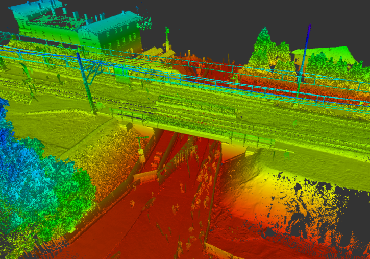
The laser scanner measures millions of surrounding points using a laser beam – it records everything it “sees”.
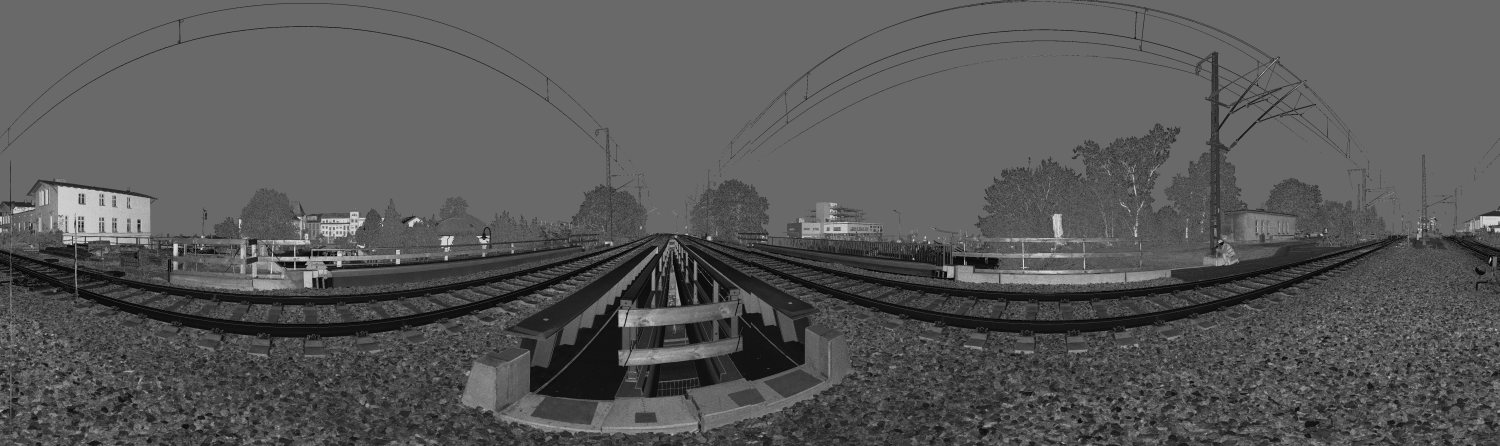
Distant elements are scanned with lower density, while closer objects are captured in much greater detail.
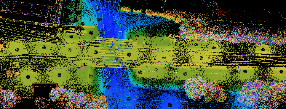
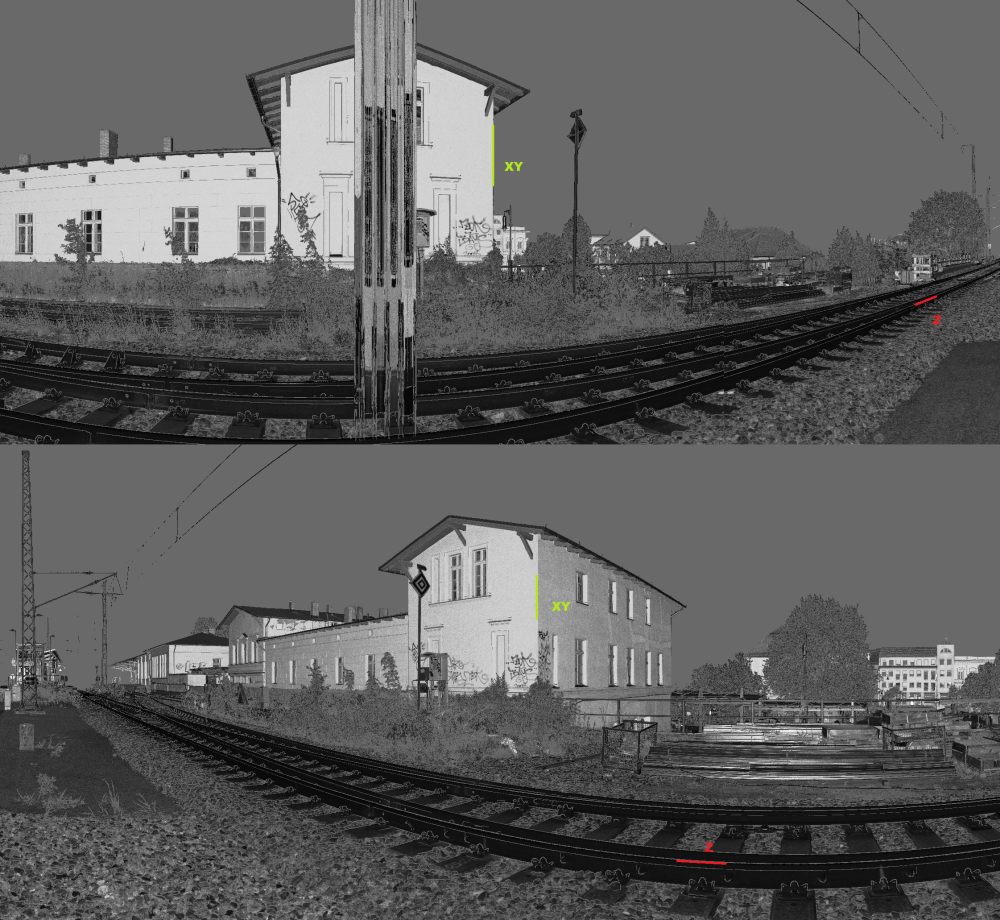
The first example shows a panoramic view representing the scanner’s field of view.
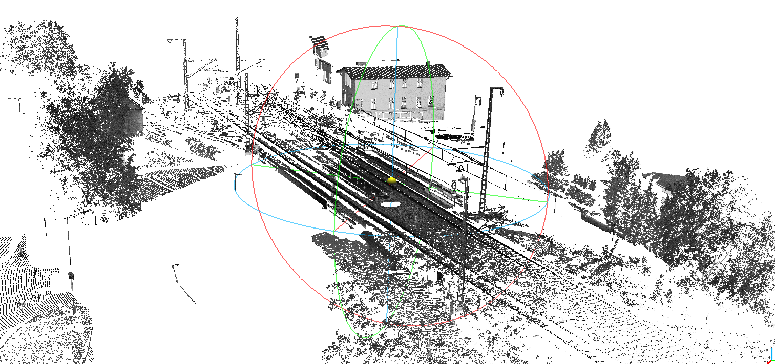
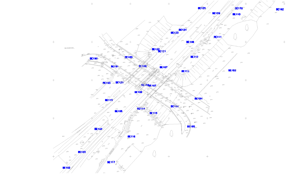
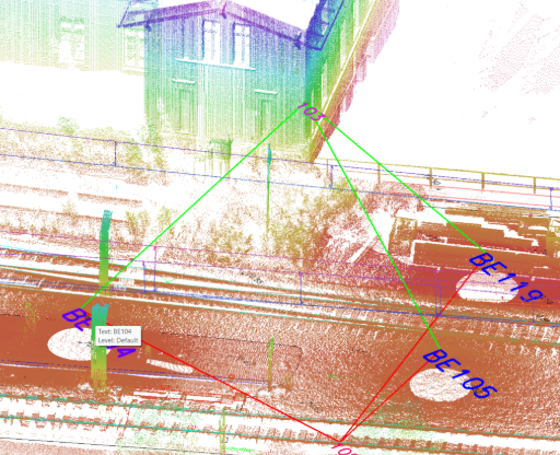
The second image presents the scanner position and its actual scanning range.
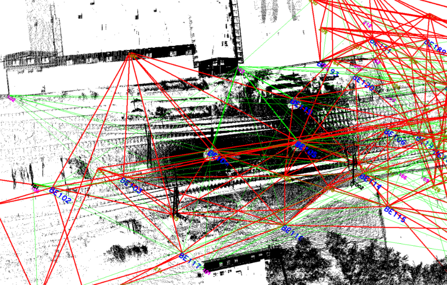
On a single project, we perform from several dozen to several thousand scans.
The visible circles indicate scanner positions, while the blue numbers identify their locations.
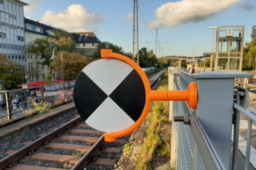
Before scanning, we place reference targets at selected locations, which are additionally measured using geodetic methods.
This allows us to obtain control point coordinates necessary for the adjustment and computation of the entire point cloud.
Registration
The determination of scanner positions is a key stage of office processing.
The calculations known as “registration” combine individual scans into a unified point cloud.
We have developed our own software based on proven geodetic methods.
We apply least squares adjustment and an indirect method in which entire scans are transformed as rigid bodies.
The transformation fulfills the condition:
∑i=1n pi vi2 → min
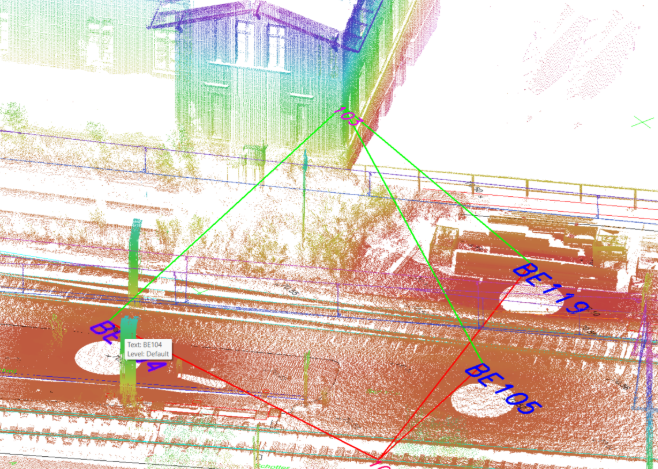
The computations are based on identifying identical elements within different scans, such as a building corner (XY) or a rail head (Z).
By measuring a sufficient number of tie points between scans, we create a dense connection network.
The computations involve shifting and rotating the scans so that the connections optimally satisfy the condition pvv = minimum.
At this stage, we maintain full control over the process.
We can detect outliers, analyze error sources, and evaluate the quality of control points.
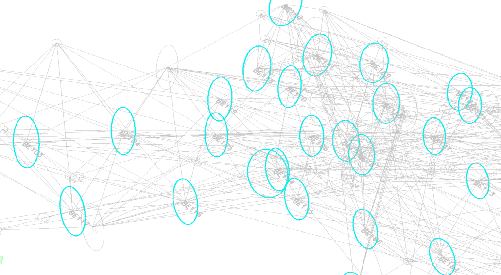
Error ellipses are an essential element in assessing calculation quality.
They indicate the level of confidence in the computed scanner coordinates.
The optimal situation occurs when the ellipses are small and close to circular.
If they become too large, we analyze the cause and take corrective actions.
This geodetic approach ensures full control over accuracy and final result quality.
The point cloud forms the foundation for all subsequent deliverables.
Errors introduced at this stage will propagate to every further phase of the project.
Therefore, we place special emphasis on quality and computational accuracy already during the registration process.
More...